So as part of a few projects I’m attempting soon I thought I best actually get a stepper motor and all the jiggery pokery to control it working.
Parts I have to play with:
- Arduino Uno SMD,
- “Dual H Bridge DC Stepper Motor Controller Board Shield L298N”
- Nema 17 stepper motor.
Great, so lets get started.
What’s a Stepper Motor?
So a stepper motor is a special type of motor. Unlike other motors such as DC and AC motors, it has a discontinuous cycle, or it moves in steps. This is due to the internal structure of the motor. It has advantages and disadvantages as with everything in life. The main advantages of stepper motors are that they are easy to control precisely without having a feedback loop, and they have a high holding torque. This makes them ideal for precision control. Unlike servo’s stepper motors will not correct their position if moved, without additional components.
There are two types of stepper motor, Unipolar and Bipolar. I’m using a Bipolar stepper motor. More information on the differing types can be found in the references at the bottom of this page.
How do we control a Stepper Motor.
We control stepper motors by setting the polarity of different coils inside the motor to different states. Tom Igoe Has a good in depth page here about how we can do this and differing methods. IMO the best method is 4 wire control and a dual H bridge. It’s simple and has the advantage that you can turn the stepper motor completely off (which you can’t do with the 2 wire method).
So here’s how I’m wiring it up (for experiment purposes).
Pins 8,9,10,11 are wire 1 thru 4. obviously Arduino needs 5v and gnd too…
The Dual H bridge takes a pair (wire 1+2) for one H bridge and a pair (wire 3+4) for the other H bridge.
My stepper motor has red and blue wires for one coil, and green and black for another coil. I’ve wired these into the outputs of each H bridge. Note that each H bridge and coil is operated completely independently of the other in terms of electronics. The H bridge will also need 5v, gnd and a voltage for the stepper motor (I’m using 5v throughout for my experiment)
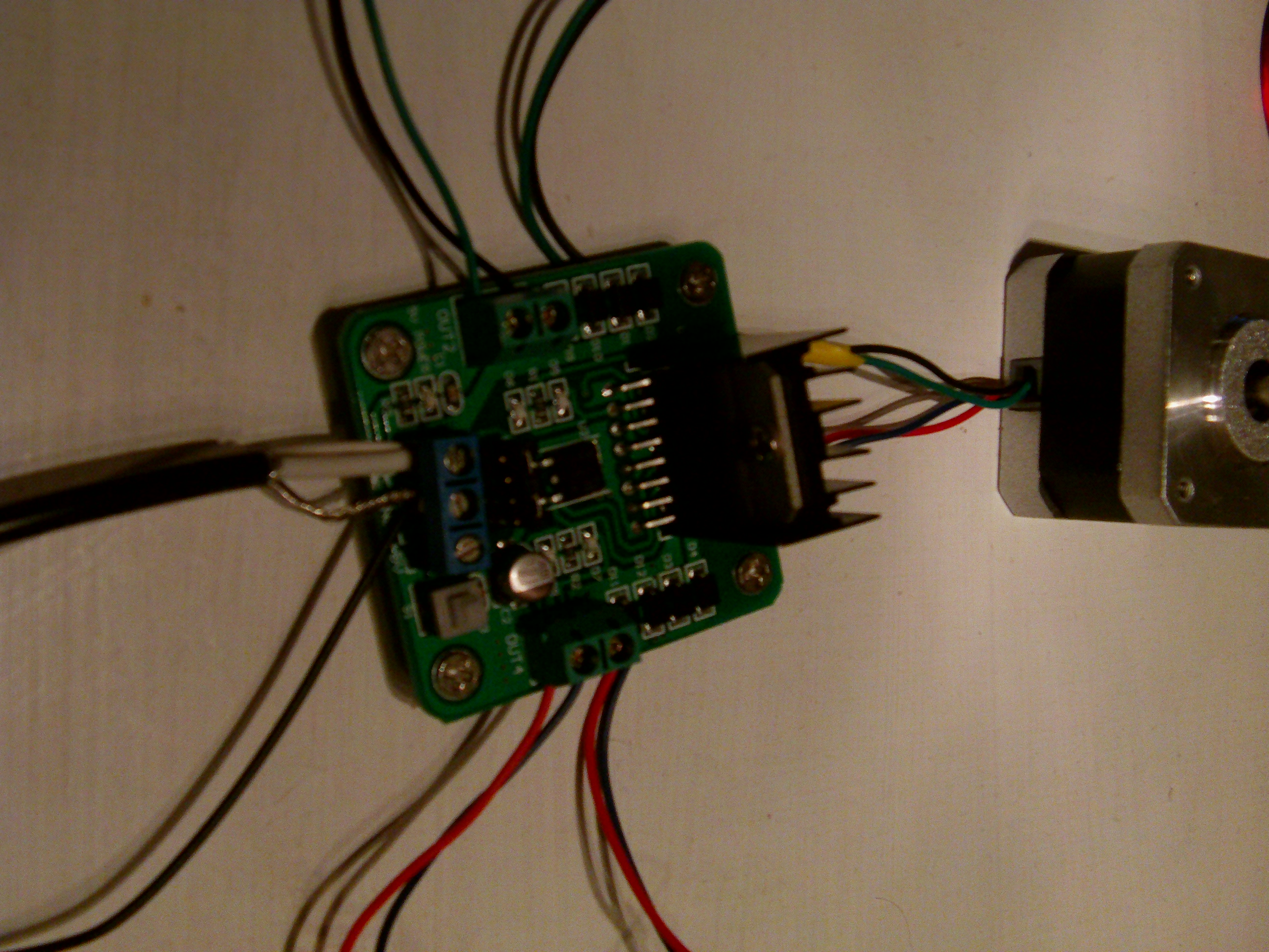
H bridge wired to a bipolar stepper motor
http://arduino.cc/en/Reference/StepperBipolarCircuit – has a good diagram of how to wire a bipolar stepper motor up to a H bridge.
http://www.youtube.com/watch?v=5nDaHJqruq0 – The first ten mins or so explains a bit more on how a H bridge is wired.
One question I came up with is which wires go with which coil? – well just use a multimeter to find this out (or maybe a datasheet?). And other is what happens if I get the order of the stepper muddled up, polarity of each coil or the coils the wrong way? The simple answer, without going into detail, is the direction of movement will change. (Easy to fix in software/firmware or swap a coils polarity at a latter point.)
Anyway here’s a simple bit of code showing how you can drive a stepper motor without any additional libraries (assuming wired as above). Change time to be the milliseconds between steps (I started at 500 and worked down to 4 (the lowest I could get to work with 5v)).
void setup() {
pinMode(8, OUTPUT);
pinMode(9, OUTPUT);
pinMode(10, OUTPUT);
pinMode(11, OUTPUT);
pinMode(13, OUTPUT);
}int time = 4;
void loop() {
digitalWrite(8, HIGH);
digitalWrite(9, LOW);
digitalWrite(10, HIGH);
digitalWrite(11, LOW);
digitalWrite(13, HIGH);
delay(time);digitalWrite(8, LOW);
digitalWrite(9, HIGH);
digitalWrite(10, HIGH);
digitalWrite(11, LOW);
digitalWrite(13, LOW);
delay(time);digitalWrite(8, LOW);
digitalWrite(9, HIGH);
digitalWrite(10, LOW);
digitalWrite(11, HIGH);
delay(time);digitalWrite(8, HIGH);
digitalWrite(9, LOW);
digitalWrite(10, LOW);
digitalWrite(11, HIGH);
delay(time);
}
Failing this you can use the example in File>Examples>Stepper>forward reverse. (OWTTE.)
I wont go into depth on using the Stepper commands that Arduino have in the library.
1 thought on “New to Stepper Motors”
Comments are closed.