So recently i was testing some old Clay Paky Pin Scans with a friend and i reached for a simple 6 channel DMX controller we had in the workshop – only to find that it was broken :(. So i thought to myself how hard can it be to make one? After all it’s simply some faders (potentiometers) some A/D and a chip to read the values and convert them to DMX code and transmit them. SIMPLE.
Well actually yes it is. Arduino offeres an open source platform for doing this and best of all – the hard work has already be done. http://www.arduino.cc/playground/Learning/DMX shows work that others have done and DMXSimple is an install-able library that makes the sending of DMX well, simple!
Within a few hours i had the code done, and my friend was working on the analogue side – the aim was to make a replacement for the broken desk with the view of if it works then we would make a 12channel and add features like variable start address’s. We originally were using a design simplified from here for the analogue side then the Arduino for the A/D and encoding. However we couldn’t get a master fader with other faders for channels to work as we would have liked – so we moved to plan B. The master and the channel values are A/Ded seprataly and the DMX output value (0-255) is calculated in the code. Unfortunately this does mean that an extra A/D channel is needed.
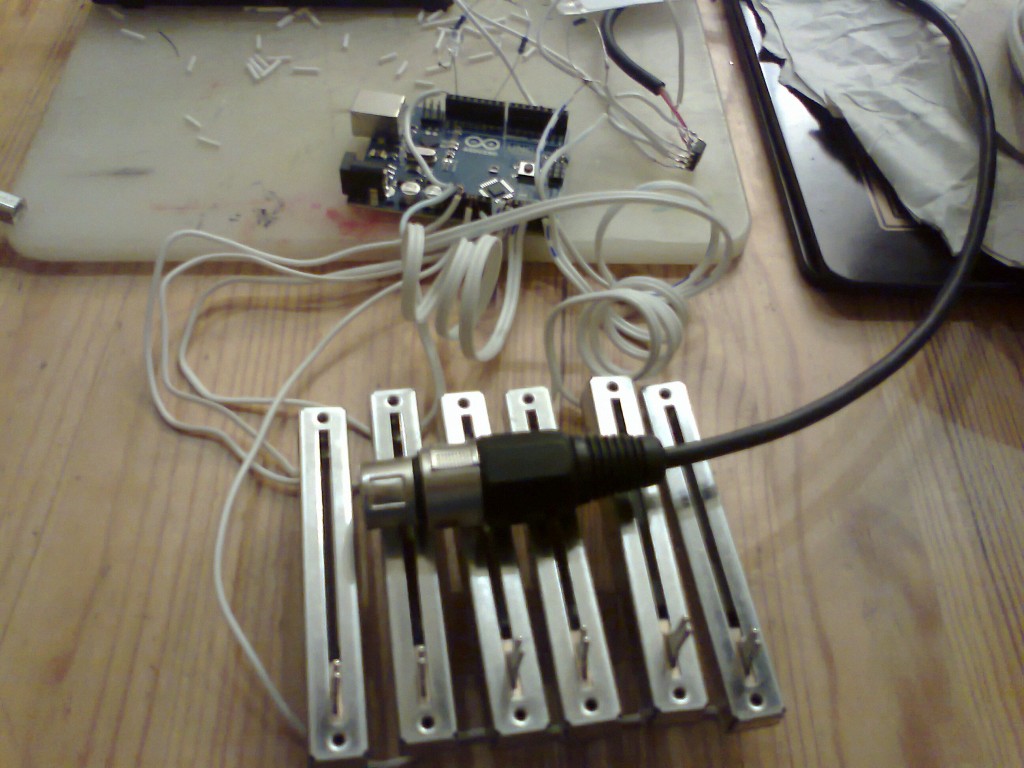
The Prototype.
So seeing as Arduino was so cheap on the ‘bay, i brought all the components needed. A Uno board, some 75176 driver chips, 100ohm resistors and some faders, wire and led’s and connectors i had around already. For £50 I had all the parts and got on with the making.
Above is a 5 channel Prototype to test my code, the DMXSimple library and if the concept would actually work. I know it’s a bit messy but it worked and that’s all it needed to do. The prototype has the faders linked at pins 1 to ground and pins 3 to the +5v on the Arduino board. Pins 2 from the faders give 0 to 5v depending on the level and are connected to the A0 to A5 pins on the Arduino. The +5v is also connected to the aref pin. The 76176 driver chip is connected as per the diagram here. It had to be 5 channel as there are only 6 analogue ins on the Arduino Uno. The ‘real’ version will use the Arduino Mega 2560, which has more in’s and outs as well as more memory.
Code:
#include <DmxSimple.h>
void setup() {
// DmxSimple.usePin(3);
// DmxSimple.maxChannel(5);
pinMode(9, OUTPUT);
}void loop() {
int chan1 = A0;
unsigned int value1 = 0;
int chan2 = A1;
unsigned int value2 = 0;
int chan3 = A2;
unsigned int value3 = 0;
int chan4 = A3;
unsigned int value4 = 0;
int chan5 = A4;
unsigned int value5 = 0;
int master = A5;
unsigned int masterval = 0;unsigned int value1a = 0;
unsigned int value2a = 0;
unsigned int value3a = 0;
unsigned int value4a = 0;
unsigned int value5a = 0;
unsigned int mastervala = 0;unsigned int value1c = 0;
unsigned int value2c = 0;
unsigned int value3c = 0;
unsigned int value4c = 0;
unsigned int value5c = 0;unsigned int value1o = 0;
unsigned int value2o = 0;
unsigned int value3o = 0;
unsigned int value4o = 0;
unsigned int value5o = 0;// read the value from the sensor:
value1 = analogRead(chan1);
value2 = analogRead(chan2);
value3 = analogRead(chan3);
value4 = analogRead(chan4);
value5 = analogRead(chan5);
masterval = analogRead(master);
//need to change from 10bit to 8bit
value1a = value1 / 4;
value2a = value2 / 4;
value3a = value3 / 4;
value4a = value4 / 4;
value5a = value5 / 4;
mastervala = masterval / 4;value1c = value1a * mastervala;
value2c = value2a * mastervala;
value3c = value3a * mastervala;
value4c = value4a * mastervala;
value5c = value5a * mastervala;//calculate the output values 0-255
value1o = value1c / 256;
value2o = value2c / 256;
value3o = value3c / 256;
value4o = value4c / 256;
value5o = value5c / 256;//output
DmxSimple.write(1, value1o);
DmxSimple.write(2, value2o);
DmxSimple.write(3, value3o);
DmxSimple.write(4, value4o);
DmxSimple.write(5, value5o);
analogWrite(9, value1o); //for testing
}
So next things for this project are a full blown 19″ rack design around the Arduino Mega, with 12 channels, a master fader, each with a flash and a master flash, variable start address and maybe DMX in also.

2 thoughts on “A simple Arduino DMX controller”
Comments are closed.